
![]() Important
Note:
Important
Note:
WITH IMMEDIATE EFFECT:
DUE TO THE UNEXPECTED GOING OUT OF BUSINESS OF AN IMPORTANT
SUPPLIER MEDIA ENGINEERING CANNOT DELIVER ANY NEW FM-SPY UNITS NOW AND
FOR THE NEXT FUTURE. WE ARE WORKING ON SOLUTIONS TO OVERCOME THIS SITUATION
ON THE FASTEST POSSIBLE WAY. WE WILL SEND OUT INFORMATION, AS SOON AS
THE PRODUCTION IS RESTARTED.
![]() Downloads:
Downloads:
FM-SPY APPLICATION 32 BIT (newest: V1.3.0: 19MB): "FMSPY13_32BIT.zip"
FM-SPY APPLICATION 64 BIT (newest: V1.3.0:
21MB): "FMSPY13_64BIT.zip"
FM-SPY
PROSPECT
(1.5MB, 4pages, format A4): "FM-SPY.pdf"
FM-SPY USER'S MANUAL(0.9MB): "FM-SPY-MANUAL.pdf"
FM-SPY
DEMO PROGRAM (3.4MB incl. 10sec data): "FM-SPY-DEMO.zip"
![]() Recommended
end user list prices (EXW Media Engineering, Switzerland):
Recommended
end user list prices (EXW Media Engineering, Switzerland):
ME-TUN: EUR
2'700.-- (tuner only, TA/TP flags, no measuring capabilties)
FM-SPY:
EUR 3'200.-- (pure measuring device, no audio outputs except phones)
FM-SPY-T: EUR 3'700.-- (measuring device with analog/digital outputs)
(our
AGENTS prices may vary slighty due to country specific import cost and
adaptations)
_____________________
![]() With
its "FM-SPY" MEDIA ENGINEERING is introducing a very versatile
and cost effective measuring device suitable for obtaining and assessing
quality parameters of FM sound broad-casting transmissions. It has been
developed under strict consideration of recommendations of the
With
its "FM-SPY" MEDIA ENGINEERING is introducing a very versatile
and cost effective measuring device suitable for obtaining and assessing
quality parameters of FM sound broad-casting transmissions. It has been
developed under strict consideration of recommendations of the
ITU-R as well as own experiences in this field of engineering.
The
"FM-SPY" is equally suitable for daily operational measurements
as well as for control measure-ments in the laboratory, in the workshop
or in the field. Thanks to its simple concept it's very easy to install
and to put into operation. The "FM-SPY" features a multitude
of functions, all of which are im-portant for measuring and evaluating
the characteristics of FM sound broadcasting transmissions. Especially
the precise seizing of frequency deviation and the power of the multiplex
signal can be out-performed according to recommendations of the ITU-R.
The results can be printed out or saved for later use and it's possible
to trigger alarm signals automatically.
The "FM-SPY" needs to be connected
to a MS WINDOWS® computer with USB-port and with a FM broadcasting
receiving antenna.
![]() BASIC
CONCEPT
BASIC
CONCEPT
The precision FM tuner built into the "FM-SPY"
receives the measuring signal via one of two antenna inputs. The selection
of the proper receiving FM frequency as well as the antenna input is outperformed
with the help of the computer program.
The FM demodulated "MPX" signal and the signal "S" representing the receiving RF signal strength are brought to two 14-Bit Analog-to-Digital converters. The resulting 14bit data words are transferred via the USB interface to the computer 400'000 times per second. The data rate on the USB interconnection is approximately 7Mbit/sec.
The MS WINDOWS® application program "FM-SPY" allows the control of the device and the selection of the measurements. The FM receiving frequency to measure can be keyed in directly while the input-ted data is rounded automatically to the smallest tuning step width of 25kHz.
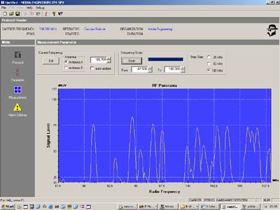
The
panorama scan function in the "FM-SPY" is presenting an overview
of all FM signals to receive plus the RF signal strength of these stations.
Scans are possible within any band limits in the FM band in steps of 25kHz,
50kHz or 100kHz. A spectral diagram is showing the RF-level versus the
receiving frequency.
After setting the tuner to the receiving
frequency the RF signal is automatically analysed. The "FM-SPY"
checks the receiving signal for a minimum signal strength and for the
amount of multipath reception. The resulting quality parameters are compared
with predefined values and a GO/NOGO decision for the further measurements
is calculated. The default threshold values are set according to recommendations
of the ITU-R but they can be changed to any numbers at any time. The "FM-SPY"
can measure independently of the result of this decision but the criterion
GO or NOGO is repeated on all measurement records together with other
measuring parameters like the actual date, the time, the measuring location,
the duration, the operators name ect.
During these preliminary decisions as well as during the following measurements the "FM-SPY" is working in strict conformity to relevant recommendations and internationally ratified specifications, in particular to Rec. CCIR-641, ITU-R BS.450-2, ITU-R BS. 412-9, ITU-R SM.1268-1.
![]() FEATURE
LOADED SOFTWARE
FEATURE
LOADED SOFTWARE
![]() The
FM-SPY application is programmed in C++ with a easy to use GUI based on
MFC libraries.
The
FM-SPY application is programmed in C++ with a easy to use GUI based on
MFC libraries.
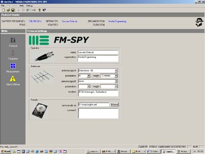
![]() In
the menu PROTOCOL the operator can
input its name, measureing location and type(s) of antennae used as well
as the name and the directory of the file containing the measureing results
In
the menu PROTOCOL the operator can
input its name, measureing location and type(s) of antennae used as well
as the name and the directory of the file containing the measureing results
.
![]() In
the menu PARAMETER the receiving
frequency and the proper antenna input A or B are selected as well as
the band limits and the step width for panorama scans in the FM band.
The graphic representation of the FM RF spectrum is useful for searching
after specific stations and for monitoring purposes as well as for the
detection of jamming signals in the vicinity of the carrier frequency
or in the frequency distance plus or minus the intermediate frequency
(IF).
In
the menu PARAMETER the receiving
frequency and the proper antenna input A or B are selected as well as
the band limits and the step width for panorama scans in the FM band.
The graphic representation of the FM RF spectrum is useful for searching
after specific stations and for monitoring purposes as well as for the
detection of jamming signals in the vicinity of the carrier frequency
or in the frequency distance plus or minus the intermediate frequency
(IF).
![]() In
the menu MEASUREMENTS different TABs
are selectable in order to choose the propre measureing task:
In
the menu MEASUREMENTS different TABs
are selectable in order to choose the propre measureing task:
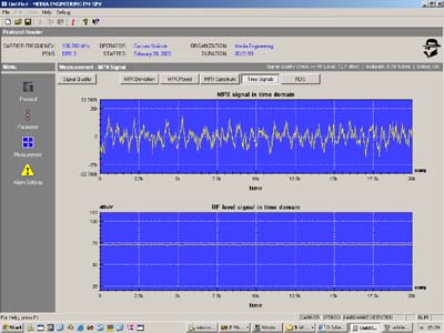
![]() In the tab SIGNAL SCOPE an oscilloscope-like
representation of repeatedly sampled clips of the "MPX" and
the "S" signal are shown.
In the tab SIGNAL SCOPE an oscilloscope-like
representation of repeatedly sampled clips of the "MPX" and
the "S" signal are shown.
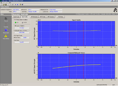
![]() In the tab SIGNAL QUALITY the RF receiving
signal quality is shown. The amount of multipath is quantified with the
maximum reflection factor [%] and with the maximum gradient of the RF
amplitude versus RF frequency [%/kHz]. The presentation is useful not
only for monitoring purposes but also while adjusting antennae.
In the tab SIGNAL QUALITY the RF receiving
signal quality is shown. The amount of multipath is quantified with the
maximum reflection factor [%] and with the maximum gradient of the RF
amplitude versus RF frequency [%/kHz]. The presentation is useful not
only for monitoring purposes but also while adjusting antennae.
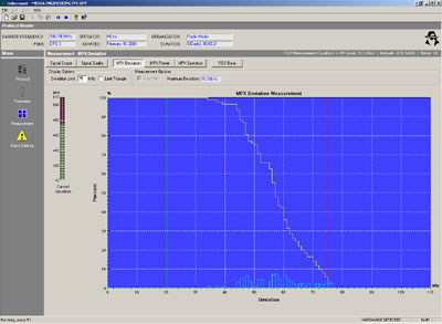
![]() In
the tab MPX DEVIATION peak frequency
deviation measurements are shown as bar graphs and statistical analysis
of these measurements in the form of a histogram of the density function
and a plot of the inverse density distribution.
In
the tab MPX DEVIATION peak frequency
deviation measurements are shown as bar graphs and statistical analysis
of these measurements in the form of a histogram of the density function
and a plot of the inverse density distribution.
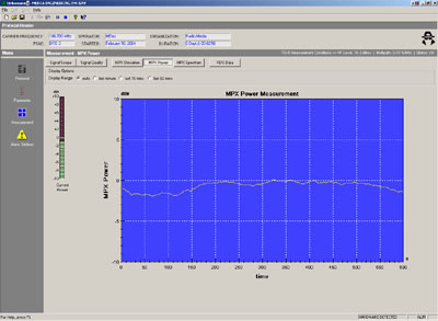
![]() In
the tab MPX POWER a curve plot is
presenting the power of the MPX signal integrated over the last 60 seconds.
The ordinate is scaled in dBr and its 0dBr mark corresponds to the +/-19kHz
frequency deviation reference of a pure sinewave modulation as recommended
and specified through the ITU-R.
In
the tab MPX POWER a curve plot is
presenting the power of the MPX signal integrated over the last 60 seconds.
The ordinate is scaled in dBr and its 0dBr mark corresponds to the +/-19kHz
frequency deviation reference of a pure sinewave modulation as recommended
and specified through the ITU-R.
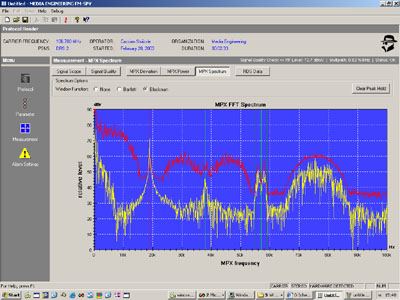
![]() In the tab MPX SPECTRUM the MPX signal
is represented in the frequency domain as the result of a 1024 point FFT
for which diverse windowing functions are selectable. Different frequency
band limits are clearly marked in the graphic in order to identify MPX
signal frequency components easily.
In the tab MPX SPECTRUM the MPX signal
is represented in the frequency domain as the result of a 1024 point FFT
for which diverse windowing functions are selectable. Different frequency
band limits are clearly marked in the graphic in order to identify MPX
signal frequency components easily.
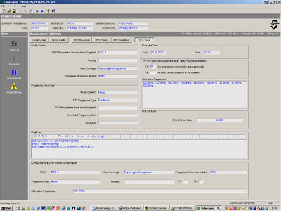
![]() In the tab RDS DATA all demodulated
and decoded RDS data is listed as well as the Bit-Error-Rate BER of the
RDS data stream.
In the tab RDS DATA all demodulated
and decoded RDS data is listed as well as the Bit-Error-Rate BER of the
RDS data stream.
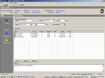
![]() In the menu ALARM SETTINGS various
alarms are defined and activated or deactivated.
Two alarming signals AL1 and AL2 are sent to front panel LEDs and potential
free optocouplers
In the menu ALARM SETTINGS various
alarms are defined and activated or deactivated.
Two alarming signals AL1 and AL2 are sent to front panel LEDs and potential
free optocouplers
![]() AUXILIARY
FEEDS AND TALLY SIGNALS
AUXILIARY
FEEDS AND TALLY SIGNALS
Different
alarm outputs and auxiliary functions are provided:
- MPX signal output, unbalanced, +6dBu at 600 Ohms, full bandwidth
- RDS-data, RDS-clock and RDS-quality digital signals
- potential free optocoupler output forRDS DETECT signal
- potential free optocoupler output for RDS TP bit (FM-SPY-T only)
- potential free optocoupler output for RDS TA bit (FM-SPY-T only)
- potential free optocoupler output for CARRIER DETECT signal
- potential free optocoupler output for STEREO DETECT signal
- potential free optocoupler output for free programmable alarm AL1 signal
- potential free optocoupler output for free programmable alarm AL2 signal
- fused +15VDC output to drive optocouplers
- SCA audio rsp. SCA data signals
![]() TECHNICAL
SPECIFICATIONS
TECHNICAL
SPECIFICATIONS
ANTENNAE
INPUTS
Number of
Antennae Inputs............................................................................
2
Antenna Input Impedance...................................................................
75 Ohms
Antenna Connector Type .................................................
F (female receptacle)
Circuit ........................................................ RF transformer
balanced earthfree
Antenna Selector Switch ........................... computer controlled
solid state switch
FM RECEIVER
Receiving Frequency Bandlimits ................................ 87.500MHz
- 108.000MHz
Receiving Frequency Tuning Step Width ......................................
25/50/100kHz
Sensitivity ...........................................................................
5uV@30dBSINAD
Intermodulation .............................................................
5mV (73dB) separation
COMPUTER
INTERFACE
Type...................................................................................................
USB1.1
Datarate ......................................................................approximate
7.6Mbit/sec
Maximum Cable Length ......................................................................
5 meters
ALARM OUTPUTS
Connector
Type ................................................... Chassis D-type,
male, 25 pin
Number of Alarm Outputs .........................................................
7 photocouplers
High isolation voltage (UL and VDE approved) ..................................
3'750 Volts
load capacity .................................................. UCEmax
= 40V / ICmax = 40mA
Additional DC Output ......................................................
+15.0 VDC, stabilized
Fusing of additional DC Output .……......................................
PTC, Ihold = 0.5A
POWER SUPPLY
Mains Power
Voltage ..............................................................
100V - 250 VAC
Mains Power Line Frequency ...........................................................
47 - 63 Hz
Power Surge ...................................................................................
< 25 Watt
PHYSICAL
DIMENSIONS
Width x
Depth x Height ........................................................
380 x 260 x 44 mm
Weight .................................................................................................
4.5 kg

PICTURE:
a view to the rear side of the FM-SPY
INCLUDED
ACCESSORIES:
1 pcs. power cord,
3wire
2 pcs. antenna connection adapter type "F-male" -"IEC-male
"
1 pcs. 19"/1RU rack mount kit
1 pcs. USB connection cable, length: 2m
1 pcs. user's manual
1 pcs. CD-ROM with application programm "FM-SPY" for MS WINDOWS®
subject
to change
© Copyright by MEDIA ENGINEERING
![]() For
further information please contact MEDIA
ENGINEERING or one of our AGENTS!
For
further information please contact MEDIA
ENGINEERING or one of our AGENTS!